By using the analogWrite() function, you can set the brightness of an LED using a PWM wave. The analogWrite function() can set a pin to output anywhere between 0-5 Volts corresponding to a digital value of 0-255. There is also an analogRead() function that is able to convert an analog input voltage of 0-5 Volts into a digital value between 0-1023.
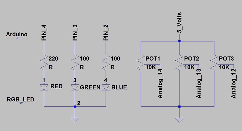
By attaching three potentiometers to three of the Analog In Pins of the Arduino we can control the color output of the RGB LED. Since an RGB LED is essentially three LEDs inside of one, you need to include a current limiting resistor for each pin. According to the data sheet on Sparkfun, the voltages for each pin are 2V Red, 3.2V Green, and 3.2V Blue. All three LEDs draw 20mA. You can calculate the minimum resistor value using:
(Source Voltage - LED Voltage) / LED Current = Resistance
Here is a terrible circuit diagram via LTSPICE:
If I weren't so lazy, I'd draw these out and scan them... maybe next time
Check out that Gray Code
// Noah Stahl
// 5/9/2011
// http://arduinomega.blogspot.com
// Arduino Mega 2560
//This project controls the output of an RGB LED using three potentiometers
//Check the blog for the circuit components and wiring
#define RLED 4 // Must be PWM pins
#define GLED 3
#define BLED 2
#define RPOT 15 //Must be Analog Input Pins
#define GPOT 14
#define BPOT 13
int red_value, green_value, blue_value;
//This function just outputs the RGB values that we read in
void color(){
analogWrite(RLED, red_value);
analogWrite(GLED, green_value);
analogWrite(BLED, blue_value);
}
void setup() {
pinMode(RLED, OUTPUT);
pinMode(GLED, OUTPUT);
pinMode(BLED, OUTPUT);
}
void loop() {
red_value = analogRead(RPOT) / 4; // 1024/256 = 4, max output value is 255
green_value = analogRead(GPOT) / 4;
blue_value = analogRead(BPOT) / 4;
color();
}
You can create a makeshift mood light by cycling through the color outputs of an RGB LED. There are only so many color combinations that actually look decent on the RGB LED, but I'm feeling a bit lazy tonight so I'm just going to randomly generate colors. At first I had the code just cycle through the basic eight RGB ON/OFF states, but I thought this would be more fun and a good exercise for my rusty programming skills.
How the algorithm works:
- Randomly assigns a value from 0-255 for the Red, Green, and Blue LEDs
- Checks to make sure that all three values are not zero
- Checks each LED to see if it's already at that value
- If current value is less than the target value, increase LED brightness
- If current value is greater than the target value, dim the LED
- Repeat until chosen values are equal to the LED outputs
// 5/9/2011
// http://arduinomega.blogspot.com
// Arduino Mega 2560
//This project will randomly cycle through an RGB LED
//Circuit uses an RGB common cathode LED attached to PWM pins
#define RLED 4 // Must be PWM pins
#define GLED 3
#define BLED 2
#define MAX 255 //Max analog value is 255,
byte RGB[3] = {0,0,0}; //Stores analog LED output values
int sel[3] = {0,0,0}; //Stores chosen LED brightness
int j;
//Function either dims or brightens RGB depending on sel[] values
void color(byte RGB[], int sel[]){
while (sel[0]!=RGB[0] || sel[1]!=RGB[1] || sel[2] != RGB[2]){ //loop until LED is equal to chosen values
for (j=0;j<3;j++){
if (sel[j]>RGB[j])(RGB[j])++; //if LED is dimmer than value, brighten LED
if (sel[j]<RGB[j])(RGB[j])--; //if LED is brighter than value, dim LED
}
analogWrite(RLED, RGB[0]); //Output analog values to RGB LED
analogWrite(GLED, RGB[1]);
analogWrite(BLED, RGB[2]);
delay(20); //slow the dim/brightening process
}
delay(1000); //wait a sec and enjoy the pretty color :3
}
void setup() {
pinMode(RLED, OUTPUT); //R LED annode attached to Pin 4
pinMode(GLED, OUTPUT); //G LED annode attached to Pin 3
pinMode(BLED, OUTPUT); //B LED annode attached to Pin 2
randomSeed(analogRead(0)); //Makes sure that random values are different each run
}
void loop() {
sel[0] = random(0,MAX+1); //decide what brightness R will be
sel[1] = random(0,MAX+1); //decide what brightness G will be
sel[2] = random(0,MAX+1); //decide what brightness B will be
if(sel[0] || sel[1] || sel[2]) color(RGB,sel); //prevents the LED from turning off
}
The randomSeed() function that you see makes sure that every time the program runs it will generate a different set of random numbers. Technically, the random() function generates psuedo-random numbers and will generate the same sequence of numbers every time you reset the Arduino unless you initialize it with a random input. By using an open floating analog input pin as your reference, you can ensure that your random numbers will be more... random.
My phone does a terrible job of recording the LED color,but does a great job of BURNING MY RETINAS
While this code works, a majority of the colors tend to be white-washed and more towards the light blue side of the color spectrum. If you were feeling adventurous, you could instead create a look-up table for the colors that you wanted to display and randomly cycle through them. This way you could create your own custom "mood light" instead of just a random color generator.
Hey, Noah!
ReplyDeleteThanks for your post. It helps me a lot!
Congratulations.
Walter.
Me too, thanks for your example!
ReplyDelete